Introducing the Internet of Things (IoT) Project Kit – a free online resource for people with no experience to learn the electronics and programming that goes into building IoT Devices.
We use affiliate links and might earn a commission at no cost to you when you make purchases for items you find on our site.
What is the Internet of Things? Think about those smart devices like your Ring Doorbell or Nest Thermostat. They all have sensors, some sort of output and connect to a network.
This project has its roots in the experience provided by Radio Shack’s Electronics Project Kit of the 70’s and 80’s. If you are too young to remember, ask your parents about Radio Shack!

If you are at the event, then you’re reading this page on a CrowView Note that is hooked up to a Raspberry Pi for the operating system.
You can also do all of this from your computer – be it Windows, macOS or Linux.
The computer is then connected to a type of Microcontroller called an Arduino.
An Arduino is an open-source electronics platform that allows you to create interactive devices and applications.
You get them on Amazon for around $20.

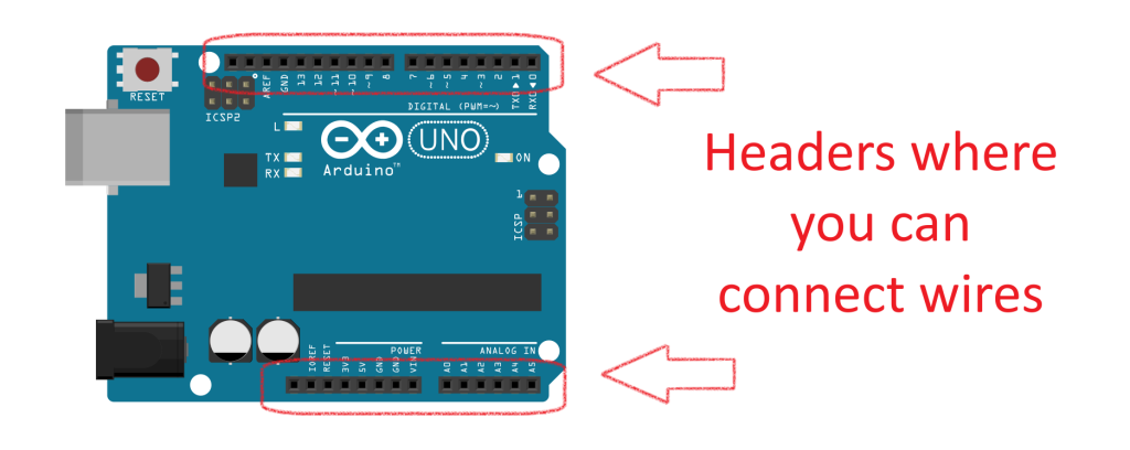
The Arduino has something called a header where you can attach wires. Those connections can either be for bringing data into the Arduino, or having it do things with other components. It might read how bright the light is in a room, or how moist some soil is. Based on that data it might turn on a light using a relay, or turn on a water valve.
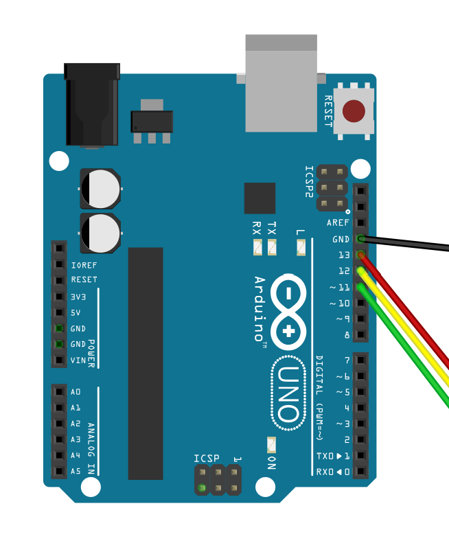
Here you can see wires connected to the 11, 12, and 13 pins as well as a GND (Ground) pin.
Next to the Arduino is a Solderless Breadboard. This allows you to prototype devices and reuse items. The two long rails that run the length are Power Rails. You often send voltage there. Positive to red and Negative to blue. These are available on Amazon for just a few dollars each.
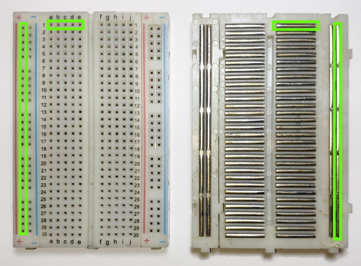
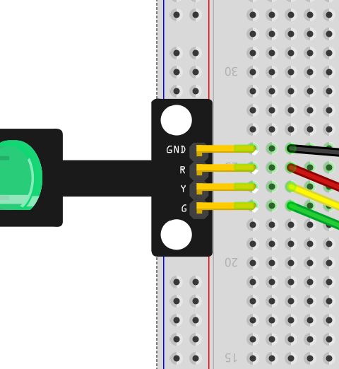
In the middle part of the breadboard are rows of connections. Each 5 are tied together. Here you can see a 3 Color LED component plugged into the breadboard. There are 4 wires plugged in, and each is connected to a pin on the component.
- The Black wire connects to the GND (Ground) lead on the Component.
- The Red wire connects to the R lead on the Component.
- The Yellow wire connects to the Y lead on the component.
- The Green wire connects to the G lead on the component.
It doesn’t matter what colored wire you use, but there are some suggested rules to follow on the site.
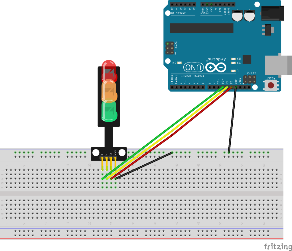
Here is a project that uses that LED to flash each color on and off. First connect the 5 wires:
- The “G” pin to pin 11.
- The “Y” pin to pin 12.
- The “R” pin to pin 13.
- We run a Ground connection from the Arduino to the power rail on the breadboard, and then another one to the GND connection on the LED Traffic Light. This makes it easier to add other components to the breadboard as almost all of them will need a Ground connection.
To make the LED go on and off, we need to instruct the Arduino to turn the power on and off to each pin. Here is the code for that:
// Sketch for HW-479
// Component: https://www.iotprojectkit.com/components/led-traffic-light-module/
// Tutorial: https://www.iotprojectkit.com/projects/traffic-lights/

// Change to the pin numbers to the pin on the Traffic Light for the color
#define GREEN_PIN 11
#define YELLOW_PIN 12
#define RED_PIN 13

// The setup() section runs once when the Arduino starts up
void setup() {
  pinMode(RED_PIN, OUTPUT);
  pinMode(YELLOW_PIN, OUTPUT);
  pinMode(GREEN_PIN, OUTPUT);
  Serial.begin(9600);
}

// The loop() section loops continuously until you turn off the Arduino
void loop() {
  digitalWrite(GREEN_PIN, HIGH);
  delay(5000);
  digitalWrite(GREEN_PIN, LOW);
  delay(200);
  digitalWrite(YELLOW_PIN, HIGH);
  delay(2000);
  digitalWrite(YELLOW_PIN, LOW);
  delay(200);
  digitalWrite(RED_PIN, HIGH);
  delay(7000);
  digitalWrite(RED_PIN, LOW);
  delay(100);
}
This code is also loaded up in a program called an Integrated Development Environment or IDE. You can use Alt-Tab to get to that program.
Now let’s add a Sonic Distance Detector.
This also is a single component project on the IoT Project Kit, but here we see it combined with the LED Traffic Lights. It needs +5V power and Ground, plus we connect the Trigger and Echo wires to pins 9 and 10 on the Arduino.
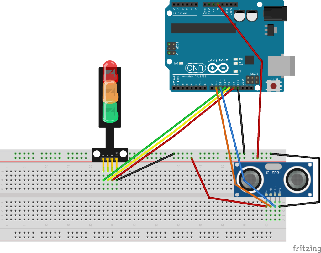
Now you can see the Power Rails on the breadboard being used.
Here is the code just to use the Sonic Distance Sensor:
// Sketch for HC-SR01 Sonic Distance Sensor
// Component: TBD
// Tutorial: TBD

// Change to the pin numbers to the pin on the Traffic Light for the color
#define TRIGGER_PIN 9
#define ECHO_PIN 10
#define RED_PIN 13

float duration;
float distance;

// The setup() section runs once when the Arduino starts up
void setup() {
  pinMode(TRIGGER_PIN, OUTPUT);
  pinMode(ECHO_PIN, INPUT);
  Serial.begin(9600);
}

void loop() {
  digitalWrite(TRIGGER_PIN, LOW);
  delayMicroseconds(2);
  digitalWrite(TRIGGER_PIN, HIGH);
  delayMicroseconds(10);
  digitalWrite(TRIGGER_PIN, LOW);

  duration = pulseIn(ECHO_PIN, HIGH);
  distance = (duration*.0343)/2;
  Serial.print("Distance Detected: ");
  Serial.println(distance);
  delay(200);
}
This just prints the distance to the console in the IDE.
Now let’s combine the two projects – changing the LEDs to tell you if you are getting too close!
// Sketch for HC-SR01 Sonic Distance Sensor
// Component: TBD
// Tutorial: TBD
// 10 is really close, 80 is someone walking up
// PWM for brightness?

// Change to the pin numbers to the pin on the Traffic Light for the color
#define GREEN_PIN 11
#define YELLOW_PIN 12
#define RED_PIN 13

#define TRIGGER_PIN 9
#define ECHO_PIN 10
#define RED_PIN 13

float duration;
float distance;

float green_threshold = 40;
float yellow_threshold = 30;
float red_threshold = 10;

// The setup() section runs once when the Arduino starts up
void setup() {
  pinMode(RED_PIN, OUTPUT);
  pinMode(YELLOW_PIN, OUTPUT);
  pinMode(GREEN_PIN, OUTPUT);

  pinMode(TRIGGER_PIN, OUTPUT);
  pinMode(ECHO_PIN, INPUT);

  Serial.begin(9600);
}

void loop() {
  digitalWrite(TRIGGER_PIN, LOW);
  delayMicroseconds(2);
  digitalWrite(TRIGGER_PIN, HIGH);
  delayMicroseconds(10);
  digitalWrite(TRIGGER_PIN, LOW);

  duration = pulseIn(ECHO_PIN, HIGH);
  distance = (duration*.0343)/2;
  Serial.print("Distance Detected: ");
  Serial.println(distance);

  if (distance < red_threshold) {
    digitalWrite(GREEN_PIN, HIGH);
    digitalWrite(YELLOW_PIN, HIGH);
    digitalWrite(RED_PIN, HIGH);
  } else if (distance < yellow_threshold ) {
    digitalWrite(GREEN_PIN, LOW);
    digitalWrite(YELLOW_PIN, HIGH);
    digitalWrite(RED_PIN, HIGH);

  } else if (distance < green_threshold) {
    digitalWrite(GREEN_PIN, LOW);
    digitalWrite(YELLOW_PIN, LOW);
    digitalWrite(RED_PIN, HIGH);
  } else {
    digitalWrite(GREEN_PIN, LOW);
    digitalWrite(YELLOW_PIN, LOW);
    digitalWrite(RED_PIN, LOW);
  }
  delay(200);
}
You can also purchase a set of 30+ Sensors for around $20 on Amazon. This is the initial core of the IoT Project Kit.
The IoTProjectKit.com will have hundreds of projects where you can learn to use individual components. There also will be more complex ones that combine multiple components.
Sign up for our Raffle!


Get The Quick Start List of Parts!
By purchasing through this page, you help support this site at no additional cost to you.
Thank you for your support!
Photo of Nest Thermostat – Photo by Dan LeFebvre on Unsplash