Before building your first project, it helps to understand a few basic concepts related to electronics, breadboards, and how components interact.
If you’re already familiar with these ideas, you can move on to Connecting the Parts.
If not, this page will give you enough context to avoid common mistakes and understand why things work the way they do.
Electronic Circuits
At its simplest, an electronic circuit is a complete path that allows electricity to flow.
A basic circuit includes:
- a power source
- one or more components
- a return path back to ground
Electricity only flows when the circuit is complete — meaning there are no gaps in the path.
If you’re new to this idea, this external guide is a good introduction:
- Basics of Electrical Circuits (B.K. Electric)
We’ll build on this concept throughout the projects on this site.
Normally Closed (NC)
The term Normally Closed (NC) means that a connection is closed by default, allowing electricity to flow.
A helpful analogy is a wire with no breaks in it.
You’ll often see NC on components like:
- relay modules
- switches
- buttons
For example, a relay may allow current to flow until it is activated, at which point the circuit opens.
Component pages will link back to this concept once they are built.
Normally Open (NO)
The term Normally Open (NO) means that a connection is open by default, preventing electricity from flowing.
An everyday analogy is an unplugged lamp — there is a gap in the circuit.
Many switches and buttons are normally open and only allow electricity to flow when pressed or activated.
As with NC, specific components will link back here as the site grows.
Breadboards
A breadboard is a reusable plastic board that allows you to prototype electronic circuits without soldering.
It contains rows and columns of holes that are internally connected in a specific pattern.
Key things to know:
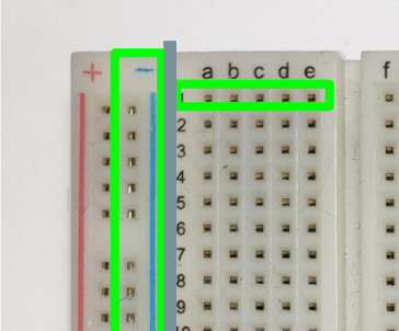
- The two long columns running vertically on each side are power rails
- typically used for voltage (+) and ground (GND)
- connected from top to bottom
- The center section is divided into rows
- each row of 5 or 6 holes is internally connected
- rows do not connect across the center gap
Because the connections are internal and not visible from the top, the image below shows the underside of a breadboard to make these connections clearer.
Breadboard connections are temporary, which makes it easy to:
- move components
- test ideas
- fix mistakes
We also have a dedicated Breadboard page that goes into more detail.
If you want an external reference:
- Using a Breadboard (sciencebuddies.org)
Input and Output
Most projects involve inputs and outputs.
Input
An input is information sent into your Arduino.
Examples include:
- button presses
- sensor readings
- rotary encoder movement
Projects on this site start with simple input examples and gradually combine multiple inputs.
Output
An output is how your Arduino affects the outside world.
Examples include:
- turning an LED on or off
- sounding a buzzer
- moving a motor
- triggering a relay
Many beginner projects focus on pairing one input with one output.
Key Coding Concepts
You do not need to be an expert programmer to use this site, but a few coding ideas will come up repeatedly:
- Variables – used to store values like sensor readings
- Program structure – setup code versus repeating logic
- Logging – sending messages to the Serial Monitor for debugging
- Debouncing – handling noisy button signals
Each of these concepts will be explained as they appear in projects, with links back to this page.
Ready to Move On?
Now that you’ve seen how circuits, breadboards, inputs, and outputs work together, you’re ready to start wiring components.
Next step: Connecting the Parts