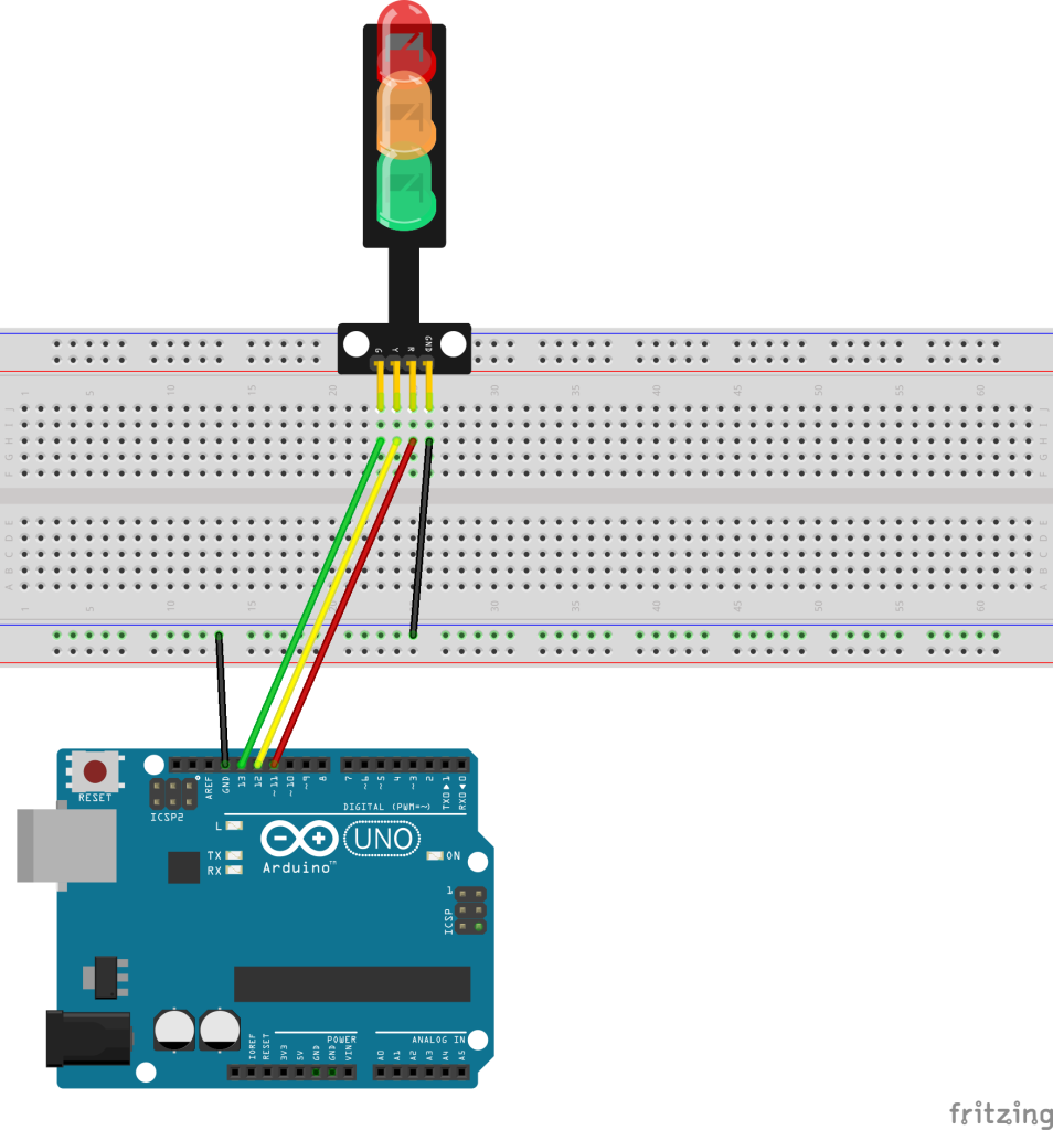
For this project we’ll connect up the LED Traffic Light Module and turn the different LEDs on in a pattern. For the simplest version of this project, you’ll use the LED Traffic Light Module and 4 wires. Once you see it working, you can modify it so that you use the power rails on the breadboard. That will make it easier to integrate this setup with other projects.
// Sketch for HW-479
// Component: https://www.iotprojectkit.com/components/led-traffic-light-module/
// Tutorial: https://www.iotprojectkit.com/projects/traffic-lights/

// Change to the pin numbers to the pin on the Traffic Light for the color
#define RED_PIN 11
#define YELLOW_PIN 12
#define GREEN_PIN 13

void setup() {
  pinMode(RED_PIN, OUTPUT);
  pinMode(YELLOW_PIN, OUTPUT);
  pinMode(GREEN_PIN, OUTPUT);
  Serial.begin(9600);
}

void loop() {
  digitalWrite(GREEN_PIN, HIGH);
  delay(5000);
  digitalWrite(GREEN_PIN, LOW);
  delay(200);
  digitalWrite(YELLOW_PIN, HIGH);
  delay(2000);
  digitalWrite(YELLOW_PIN, LOW);
  delay(200);
  digitalWrite(RED_PIN, HIGH);
  delay(7000);
  digitalWrite(RED_PIN, LOW);
  delay(100);
}
You can combine the schematic from this project with project to build project.